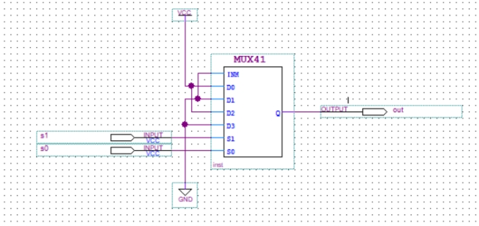
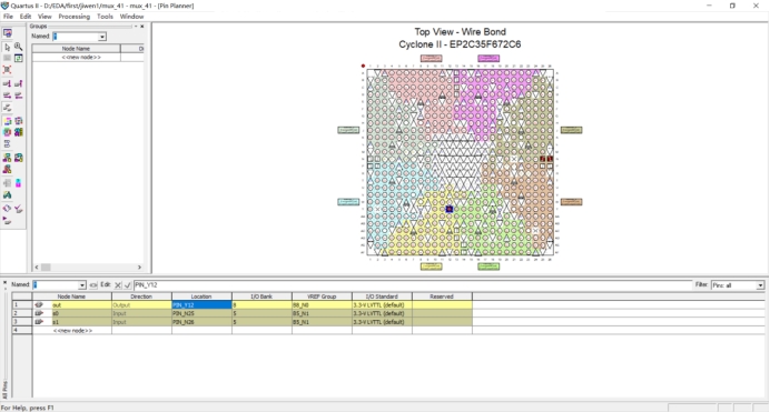
library ieee; use ieee.std_logic_1164.all; entity mux_41 is port( s : instd_logic_vector(1downto0); y : outstd_logic); endentity mux_41; architecture archmux of mux_41 is begin mux4_1: process (s) begin if s = "00"then y <= '1'; elsif s = "01"then y <= '0'; elsif s = "10"then y <= '1'; else y <= '0'; endif; endprocess mux4_1; endarchitecture archmux;
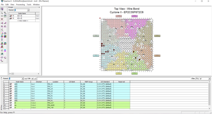
library ieee; use ieee.std_logic_1164.all; entity mv4 is port ( a : instd_logic_vector(3downto0); b : instd_logic_vector(3downto0); bt,st,eq : outstd_logic); endentity mv4; architecture behave of mv4 is begin p1 : process (a,b) begin if (a>b) then bt<='1';eq<='0';st<='0'; elsif (a<b) then bt<='0';eq<='0';st<='1'; elsif (a=b) then bt<='0';eq<='1';st<='0'; endif; endprocess p1; endarchitecture behave;
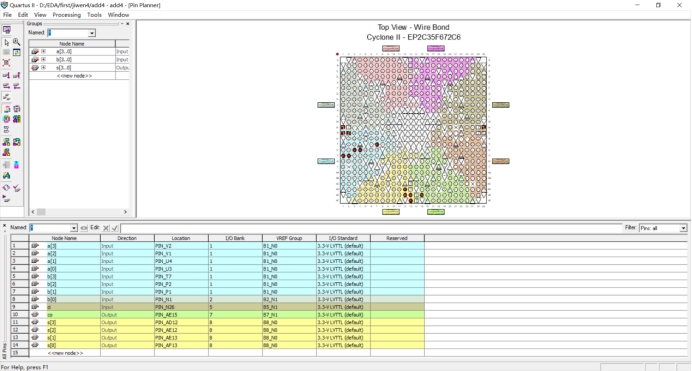
entity add4 is port(a,b:instd_logic_vector(3downto0); ci:instd_logic; s:outstd_logic_vector(3downto0); co:outstd_logic); endentity; architecture add_4 of add4 is SIGNAL c0,c1,c2:std_logic; begin s(0) <= a (0) xor b(0) xor ci; c0<= (a(0) and b(0)) or (a(0) and ci) or (b(0) and ci); s(1) <= a (1) xor b(1) xor c0; c1<= (a(1) and b(1)) or (a(1) and c0) or (b(1) and c0); s(2) <= a (2) xor b(2) xor c1; c2<= (a(2) and b(2)) or (a(2) and c1) or (b(2) and c1); s(3) <= a (3) xor b(3) xor c2; co<= (a(3) and b(3)) or (a(3) and c2) or (b(3) and c2); endarchitecture add_4;