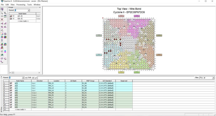
library ieee; use ieee.std_logic_1164.all; entity seven is port( a: instd_logic_vector(3downto0); b: outstd_logic_vector(6downto0)); endentity seven;
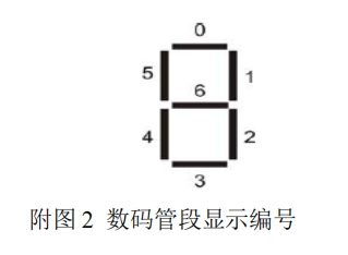
architecture behave of seven is begin p1:process(a) begin case a is when"0000"=>b<="1000000"; when"0001"=>b<="1111001"; when"0010"=>b<="0100100"; when"0011"=>b<="0110000"; when"0100"=>b<="0011001"; when"0101"=>b<="0010010"; when"0110"=>b<="0000010"; when"0111"=>b<="1111000"; when"1000"=>b<="0000000"; when"1001"=>b<="0010000"; when"1010"=>b<="0001000"; when"1011"=>b<="0000011"; when"1100"=>b<="1000110"; when"1101"=>b<="0100001"; when"1110"=>b<="0000110"; when"1111"=>b<="0001110"; endcase; endprocess; endarchitecture behave;
entity add4 is port(a,b:instd_logic_vector(3downto0); ci:instd_logic; s:outstd_logic_vector(3downto0); co:outstd_logic); endentity; architecture add_4 of add4 is SIGNAL c0,c1,c2:std_logic; begin s(0) <= a (0) xor b(0) xor ci; c0<= (a(0) and b(0)) or (a(0) and ci) or (b(0) and ci); s(1) <= a (1) xor b(1) xor c0; c1<= (a(1) and b(1)) or (a(1) and c0) or (b(1) and c0); s(2) <= a (2) xor b(2) xor c1; c2<= (a(2) and b(2)) or (a(2) and c1) or (b(2) and c1); s(3) <= a (3) xor b(3) xor c2; co<= (a(3) and b(3)) or (a(3) and c2) or (b(3) and c2); endarchitecture add_4;
LIBRARY IEEE; use ieee.std_logic_1164.all; use ieee.std_logic_unsigned.all; entity add8 is port(a8,b8:instd_logic_vector(7downto0); ci8:instd_logic; s8:outstd_logic_vector(7downto0); co8:outstd_logic); endentity; architecture add_8 of add8 is component add4 is port(a,b:instd_logic_vector(3downto0); ci:instd_logic; s:outstd_logic_vector(3downto0); co:outstd_logic); endcomponent; signal c:std_logic; begin
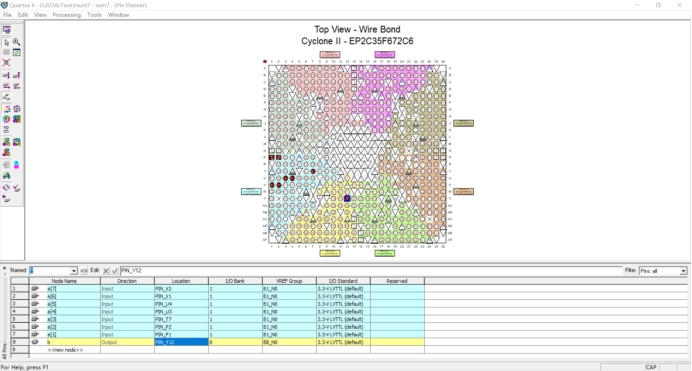
LIBRARY IEEE; use ieee.std_logic_1164.all; use ieee.std_logic_unsigned.all; entity sum7 is port (a:instd_logic_vector(7downto1); b:outstd_logic); endentity; architecture behave of sum7 is begin process(a) variable sum: integerrange0to7; begin sum:=0; if a(7)='1'then sum:=sum+1;endif; if a(6)='1'then sum:=sum+1;endif; if a(5)='1'then sum:=sum+1;endif; if a(4)='1'then sum:=sum+1;endif; if a(3)='1'then sum:=sum+1;endif; if a(2)='1'then sum:=sum+1;endif; if a(1)='1'then sum:=sum+1;endif; if sum>3then b<='1'; else b<='0'; endif; endprocess; endarchitecture;